
RH refining method is the German steel company Ruhrstahl and Heraens joint in 1958 the successful development of the vacuum cycle degassing method. RH refining technology because of its good degassing effect, less cooling, wide application and so on, so far the world has been widely used in iron and steel industry.
FURNACE STRUCTURE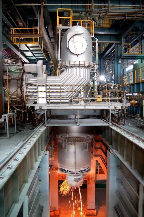
The main parts of the RH refining furnace have different functions and positions according to the different functions and positions in the furnace refining, which are respectively called: dipping pipe, circulation pipe, lower tank, middle tank (including alloy charging port), upper tank, Also known as hot bend) (including manhole) and other parts.
REFRACTORY LINING STRUCTURE
- The bottom of the tank is divided into: working layer, sub-working layer, ramming material.
- The lower slot is divided into: working layer, sub-working layer, insulation layer (also known as permanent layer), insulation layer.
- The middle slot is divided into: working layer, sub-working layer, insulation layer (also known as the permanent layer), insulation layer.
- Alloy feeding mouth is divided into: hot part of the working layer, insulation layer
- Chute part is divided into: working layer, sub-working layer, insulation layer
- The upper slot is divided into: working layer, sub-working layer, insulation layer (also known as permanent layer), insulation layer.
- Hot roof is divided into: working layer, insulation layer (also known as permanent layer), insulation layer.
- Manhole: working layer, insulation layer.
RH furnace refractory lining life, because of their different parts and different. RH furnace working state is part of the furnace away from the molten steel, some from the molten steel to be close to some, or even insert the molten steel, refractory life depends on the use of parts, Corrosion damage the most serious, followed by the bottom, other parts of the damage lighter. RH degassing vacuum liner lining material according to their location and away from the molten steel and the tank by the temperature, vacuum, gas, chemical, thermal and other factors to determine.
RH system operating process
After hoisting the ladle laden with molten steel to the processing position, the vacuum chamber of the RH unit is turned over the ladle.
And then down the vacuum chamber will be inserted into the molten steel pipe, the insertion depth should not be less than 150mm-200mm.
After the start of the vacuum pump, with the vacuum chamber pressure drop, Hong Kong in the molten steel along the two pipes into the riser tube blowing into the driving gas, when the vacuum chamber pressure dropped to 26-13Pa, the molten steel in the vacuum chamber Of the cycle to the very obvious.
The driving gas is present in the molten steel in the form of a large number of small bubbles.
Due to the role of high temperature and low pressure, gas expansion work to promote the liquid steel in the riser in the rapid increase.
When the liquid steel from the riser into the vacuum chamber, the line speed of up to 5 m / s, so the molten steel was fountain-like into the vacuum chamber, the degassing interface significantly increased, thereby accelerating the degassing process.

RH system refractory materials configuration
- Impregnation tube: Fused re-bonded magnesia-chrome bricks (LDMGe-20) (immersion salt).
- Circulating tube: fused re-bonded magnesia-chrome brick (LDMGe-26 / -20) (immersion salt).
- Impregnated pipe outer wall and steel outer wall protection material: corundum spinel castable (LGJJ-1)
- Tank bottom working layer: fused re-bonded magnesia-chrome bricks (LDMGe-20) (immersion salt).
- Secondary working layer: fused re-bonded magnesia-chrome bricks (LDMGe-20) (immersion salt).
- Ramming material: magnesium chromium ramming compound (LMCR-20).
- Lower trough working layer: fused re-bonded magnesia-chrome bricks (LDMGe-20) (immersion salt).
- Secondary working layer: fused recombination / direct bonding magnesia-chrome bricks (LDMGe-20) (LZMGe-12,8).
- Insulation: high-alumina brick / mullite-light ball light brick / light high-alumina bricks.
- Insulation layer: calcium silicate board (Ⅱ-200).
- Middle trough working layer: fused re-bonded magnesia-chrome bricks (LDMGe-20).
- Secondary working layer: Directly bonded magnesia-chrome bricks (LZMGe-18, LZMGe-12, LZMGe-8).
- Insulation: high-alumina brick / mullite-light ball light brick / light high-alumina bricks.
- Insulation layer: calcium silicate board (Ⅱ-200).
- Alloy feed port
- (LDMGe-20) (LDMGe-26) / semi-re-bonded magnesia-chrome bricks (LBMGe-20) The hot-working layer:
- Thermal insulation layer: calcium silicate board (Ⅱ-200).
- Chute working layer: silicon nitride bonded silicon carbide impact zone
- (LBMGe-20) / semi-re-bonded magnesia-chrome bricks (LBMGe-20)
- Chute times working layer: high alumina brick / light ball light weight brick / light high alumina brick.
- Chute Insulation: Aluminum Silicate Felt (PXZ-1000)
- Upper trough working layer: fused re-bonded magnesia-chrome bricks (LDMGe-20) / semi-re-bonded magnesia-chrome bricks (LBMGe-20).
- Secondary working layer: Directly bonded magnesite chrome brick (LZMGe-18) (LZMGe-12) (LZMGe-8).
- Insulation: high-alumina brick / mullite-light ball light brick / light high-alumina bricks.
- Insulation layer: calcium silicate board (Ⅱ-200).
- Hot cover
- Working layer: Directly bonded magnesite chrome brick (LZMGe-18) (LZMGe-12) (LZMGe-8).
- Sub-working layer: high alumina brick / clay brick (N-2a) / light high alumina brick. .
- Insulation layer: calcium silicate board (Ⅱ-200).
- Magnesium-chrome grout (LMGeN-18/8) and high-aluminum mud (LN-65) are used for masonry.